
-
About UsThe headquarters of Tianjin Lingjie Transmission Technology Co., Ltd. is located in Tianjin Binhai High-tech Zone. It is an electromagnetic clutch manufacturer and a high-tech enterprise integrating R & D and manufacturing. Products are widely used in missile silos, German Leica medical equipment, rail transit equipment, smart gates, robots, CCTV stage equipment, motor brakes, port equipment, CNC machine tools, motors, cement equipment, civil air defense equipment, packaging machinery, printing machinery, Paper machinery, textile machinery, office equipment, metallurgical machinery, tobacco machinery, automated production equipment and many other mechanical transmission systems as executive components, so as to complete the clutch, reversing, speed change, braking, positioning and other functions.
 营销与服务业务咨询电话:
 -
Products
 营销与服务业务咨询电话:
 -
BlogOur products are exported to Europe, America, Africa, Southeast Asia and other countries. Currently, the overseas offices are located in Ohio, Hamburg, Germany and Kuala Lumpur, Malaysia. The company's customers are all over the world, among which our company is the product supporting manufacturers of German Leica, IFE rail vehicle door system, Jie Shun Technology, Shenzhen Simorro and other companies. Creating value for the society with scientific and technological innovation is my eternal pursuit of agile transmission. "Integrity, responsibility and win-win" is our consistent goal.
 营销与服务业务咨询电话:
 -
Industry Applications
 营销与服务业务咨询电话:

Share
- Details
-
The jaw-type electromagnetic clutch uses the current passed into the excitation coil in the yoke to generate a magnetic force to attract the armature, thereby engaging the two upper tooth-shaped pawls connected to the yoke and the armature to transmit torque. The jaw-type electromagnetic clutch can be divided into two types: coil rotation (with slip ring type) and coil stationary (without slip ring type). The former excitation coil rotates, and the current is introduced through the slip ring. The latter excitation coil is stationary and the current Directly pass into the coil. Tailing electromagnetic clutch is suitable for various types of mechanical transmission systems, and plays the role of clutch, inching, speed change, and reversing.
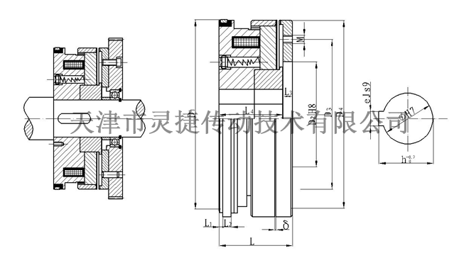
The embedded electromagnetic clutch generates a magnetic force to attract the armature by means of an electric current flowing into an excitation coil in the yoke, thereby engaging two upper tooth-shaped pawls connected to the yoke and the armature to transmit torque. The jaw-type electromagnetic clutch can be divided into two types: coil rotation (with slip ring type) and coil stationary (without slip ring type). The former excitation coil rotates, and the current is introduced through the slip ring. The latter excitation coil is stationary and the current Directly pass into the coil. In order to make it easy to separate and close, triangular teeth or trapezoidal teeth are generally used. The following figure shows the coil rotating jaw electromagnetic clutch. The upper part of the figure is in the engaged state and the lower part is in the disengaged state. The drive gear 1 is mounted on a rolling bearing on a shaft 9, and the armature 3 and the yoke 8 have triangular teeth on opposite end faces, and the field coil 6 is placed in the yoke. The internal meshing gear pair between parts 2 and 3 has the dual functions of guiding and transmitting torsion. After the coil is energized to establish a magnetic field, the yoke attracts the armature, and the end teeth mesh. The power is transmitted from the gear 1 to the engaged armature and yoke through the ring gear 2, and is output by the shaft 9. When the clutch is de-energized, the compression spring 7 resets the armature, and the two halves of the clutch teeth are separated. The function of the magnetic isolation ring 4 is to make the magnetic lines of force form a loop, reduce magnetic loss and increase the engagement force.Main performance parameters
Main Technical DataSpecifications
SizeRated transmission torque
Rated Transmitting Torque (N.m)Rated voltage
Rated Voltage
D.C(V)Coil power consumption (20 ℃)
Coil power(20℃) WMaximum allowable combined speed
Max Engagement Speed
r/minMaximum allowable speed
Max Allowed Speed
(r/min)2.5
25
24
46
60
5000
8
80
24
77
30
4000
15A
150
24
98
30
3500
30A
300
24
62
15
3000
Installation Schematic
Installation Diagram
Outline and installation dimensions
Shape and Installation DimensionsSpecifications Model
Radial Dimensions
Axial Dimensions
Brush model
Brush ModelD1
D2
D3
D4
Φ
h
e
M
L
L1
L2
L3
L4
Δ
2.5
100
35
—
100
25
28.3
8
——
45
3
8
7.5
38
0.25±0.05
DS-002
8
134
70
100
134
40
43.3
12
6-M8
65
2.5
10
7.7
60
0.3±0.05
DS-008
15A
166
90
120
166
35
38.3
10
3-M12
78
2
10
10
68.2
0.3±0.05
30A
200
100
140
200
50
53.8
14
4-M12
94
3
10
13
80.5
0.35±0.05
DLYH1 series power loss jaw electromagnetic clutch
Classification
Keyword
Jaw electromagnetic clutch
- Details
-
The jaw-type electromagnetic clutch uses the current passed into the excitation coil in the yoke to generate a magnetic force to attract the armature, thereby engaging the two upper tooth-shaped pawls connected to the yoke and the armature to transmit torque. The jaw-type electromagnetic clutch can be divided into two types: coil rotation (with slip ring type) and coil stationary (without slip ring type). The former excitation coil rotates, and the current is introduced through the slip ring. The latter excitation coil is stationary and the current Directly pass into the coil. Tailing electromagnetic clutch is suitable for various types of mechanical transmission systems, and plays the role of clutch, inching, speed change, and reversing.
The embedded electromagnetic clutch generates a magnetic force to attract the armature by means of an electric current flowing into an excitation coil in the yoke, thereby engaging two upper tooth-shaped pawls connected to the yoke and the armature to transmit torque. The jaw-type electromagnetic clutch can be divided into two types: coil rotation (with slip ring type) and coil stationary (without slip ring type). The former excitation coil rotates, and the current is introduced through the slip ring. The latter excitation coil is stationary and the current Directly pass into the coil. In order to make it easy to separate and close, triangular teeth or trapezoidal teeth are generally used. The following figure shows the coil rotating jaw electromagnetic clutch. The upper part of the figure is in the engaged state and the lower part is in the disengaged state. The drive gear 1 is mounted on a rolling bearing on a shaft 9, and the armature 3 and the yoke 8 have triangular teeth on opposite end faces, and the field coil 6 is placed in the yoke. The internal meshing gear pair between parts 2 and 3 has the dual functions of guiding and transmitting torsion. After the coil is energized to establish a magnetic field, the yoke attracts the armature, and the end teeth mesh. The power is transmitted from the gear 1 to the engaged armature and yoke through the ring gear 2, and is output by the shaft 9. When the clutch is de-energized, the compression spring 7 resets the armature, and the two halves of the clutch teeth are separated. The function of the magnetic isolation ring 4 is to make the magnetic lines of force form a loop, reduce magnetic loss and increase the engagement force.Main performance parameters
Main Technical DataSpecifications
SizeRated transmission torque
Rated Transmitting Torque (N.m)Rated voltage
Rated Voltage
D.C(V)Coil power consumption (20 ℃)
Coil power(20℃) WMaximum allowable combined speed
Max Engagement Speed
r/minMaximum allowable speed
Max Allowed Speed
(r/min)2.5
25
24
46
60
5000
8
80
24
77
30
4000
15A
150
24
98
30
3500
30A
300
24
62
15
3000
Installation Schematic
Installation DiagramOutline and installation dimensions
Shape and Installation DimensionsSpecifications Model
Radial Dimensions
Axial Dimensions
Brush model
Brush ModelD1
D2
D3
D4
Φ
h
e
M
L
L1
L2
L3
L4
Δ
2.5
100
35
—
100
25
28.3
8
——
45
3
8
7.5
38
0.25±0.05
DS-002
8
134
70
100
134
40
43.3
12
6-M8
65
2.5
10
7.7
60
0.3±0.05
DS-008
15A
166
90
120
166
35
38.3
10
3-M12
78
2
10
10
68.2
0.3±0.05
30A
200
100
140
200
50
53.8
14
4-M12
94
3
10
13
80.5
0.35±0.05
Product inquiry

The company has a product research and development department composed of experts, senior engineers and other professional and technical personnel. It is engaged in research and development and has perfect research and development test equipment. At present, the products reach more than 100 series of nearly 1,000 specifications, and the force distance ranges from 0.1N. m ~ 250000N.m. The company has been rated as a high-tech enterprise by the state for more than ten consecutive years, and a number of R & D projects have been established locally and have received municipal financial support.
Service Hotline:
Sales Department: Xu Jie
Sales Phone:+86-22-26616372, +86-22-26341260, +86 13920613215
Fax: 86-022-26616580
Market Development Department: Li Shuo
Marketing Department Telephone:+86-22-26614130
Technology Department: Yue Chao
Technical Department Telephone:+86-22-26222775 ,+86 18602228435
QQ:1059237223 1611412939
Company Website:www.tjlhq.com
Enterprise E-mail:xzm@tjlhq.com
Company address: No.6, Zone B, South Jifeng Road, Hongcang City Industrial Park, Yanji Daohong, Beichen District, Tianjin