Share
- Details
-
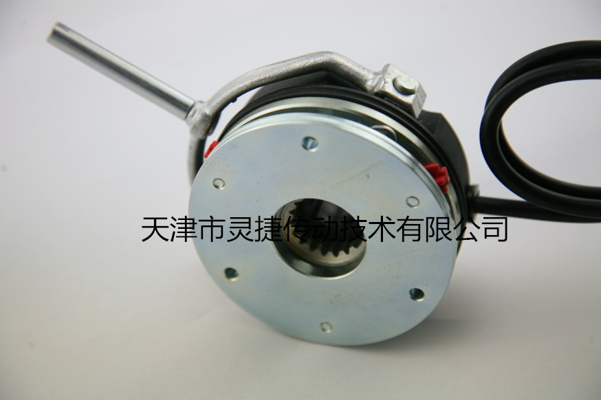
Electromagnetic deenergization brake (non-excited electromagnetic brake) is a friction plate brake pressed by a spring when the electromagnetic disengagement (release) is de-energized. It can be matched with electric motor into a new type of brake motor, and can also be used in mechanical transmission system to realize fast parking and accurate positioning. It can be used in occasions such as safe (anti-dangerous) braking when power is off.
Electromagnetic power-off brake (non-excited electromagnetic brake) has the advantages of simple structure, wide adaptability, low noise, and reliable braking. It is widely used in various mechanical transmission devices. It is an ideal in industrial modernization. Executive component.
Electromagnetic power-off brake (non-excitation type electromagnetic brake) can be used safely under the condition that the relative humidity of the surrounding air is not more than 85%. Class B insulation is adopted around the brake, and the voltage fluctuation does not exceed 5% and-15% of the rated voltage. Its working mode is continuous working system.
Note: After installation, the hollow bolt must be unscrewed and locked on the rear end cover or flange of the motor.
Electromagnetic power-off brake (power-off brake) has the advantages of compact structure, convenient installation, wide adaptability, low noise, high working frequency, sensitive action, and reliable braking. It is an ideal automatic actuator.
The main material of electromagnetic power-off brake: iron core and armature are mostly made of No. 10 steel. For large brakes, No. 8 steel is mostly used. The winding generally uses F-grade heat-resistant grade. The friction disc generally requires a friction coefficient of more than 0.5. There are also springs.
The brake is externally connected with a half-wave rectifier to rectify single-phase alternating current into direct current. After the winding is energized, a magnetic field is generated, which attracts the armature back, and the armature compresses the spring fixed in the core.The electromagnetic power-off brake of the motor is completed by the brake, which is divided into two categories: power-on brake and power-off brake. The power-on brake is used for braking occasions requiring precise positioning, and the power-off brake is used for occasions where the equipment must be reliably stopped after power failure: that is, if the equipment cannot be stopped in time after power failure, it will cause casualties, equipment damage, product scrapping and other serious accidents that endanger safe production.
The working mechanism of the electromagnetic power-off brake is that the brake does not restrict the rotating shaft when the motor is energized, and when the motor is powered off or the motor is powered off for any reason, the braking function of the electromagnetic power-off brake is activated, the motor rotating shaft is locked, and the motor rotor is converted from dynamic to static in a short time, and the equipment is transferred to a reliable parking state.
An electric motor is a device that converts electrical energy into mechanical energy. The starting process of the motor will undergo a state transition from static to dynamic; after the motor is powered off during operation, it will undergo a transition from dynamic to static due to inertia. Most equipment has no requirement for the length of time from moving to static, but some equipment such as elevators, cranes, automated production lines, etc. must be stopped within a very short period of time after power failure, which introduces our topic today, motor brake control.


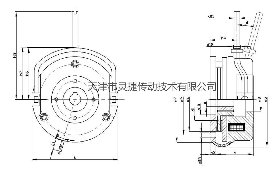
Main performance parameters and installation dimensions

Seat Number
b
dH7 standard
d1
d2
d3H7
d5
d6j7
d7
d8
d10
d11
d12
d13
d14
d15
di
da
06
88
10/11/12/14/15
3 × M4
72
25
91
87
87
52
31
8
9.6
4 × M4
37.7
3 × 4.5
40
60
08
106.5
11/12/14/15/20
3 × M5
90
32
106
102
102
60
41
8
9.6
4 × M5
49
3 × 5.5
47
77
10
132
11/12/14/15/20
3 × M6
112
42
134
130
130
68
45
10
12
4 × M5
54
3 × 6.6
66
95
12
152
20/25
3 × M6
132
50
155
150
150
82
52
10
12
4 × M5
64
3 × 6.6
70
115
14
169
20/25/30
3 × M8
145
60
169
165
165
92
55
12
14
4 × M6
75
3 × 9
80
124
16
189
25/30/35/38*
3 × M8
170
68
195
190
190
102
70
12
/
4 × M6
85
3 × 9
104
149
18
216
30/35/40/45
3 × M8
196
75
222
217
217
116
77
14
/
4 × M8
95
6 × 9
129
174
20
249
35/40/45/50
3 × M10
230
85
259
254
254
135
90
14
/
4 × M10
110
6 × 11
148
206
25
296
40/45/50/55/60/65/70*
3 × M10
278
115
307
302
302
165
120
16
/
4 × M10
140
6 × 11
199
254
30
356
65/70/75/80
3 × M10
325
140
365
363
363
200
145
18
/
4 × M10
180
6 × 11
230
300
■Standard voltage: 24VDC、180VDC、205VDC。
■MK: Rated torque (Nm) This value is measured when the relative speed Δn = 100rpm.
■P: at 20.C coil power (W).
■Keyway standard reference GB/T1095The choice of shaft diameter depends on the type of load. Refer to GB/T1566 for the standard of keyway marked with * for shaft hole.
■L1is the leader length.
■Unit: mm.
Seat Number
h
h1 min
h1 max
h2
h3
h4
h5
h6
h7
h8
L
L1
S
Smax
Α
Beta
06
36.3
39.3
43.25
1
6
15.8
107
54.5
56.3
1
18
500
0.2
0.5
25°
12°
08
42.8
46.8
50.8
1.5
7
16.3
116
63
65
1
20
500
0.2
0.5
25°
10°
10
48.4
52.4
55.9
2
9
27.4
132
73.8
77.8
1
20
500
0.2
0.5
25°
9°
12
54.9
58.9
67.53
2
9
29.4
161
85
88.5
1.5
25
500
0.3
0.75
25°
10°
14
66.3
71.3
77.3
2
11
33
195
98
101.5
1.5
30
500
0.3
0.75
25°
9°
16
72.5
77.5
85.5
2.25
11
37.5
240
/
/
1.5
30
700
0.4
0.75
25°
10°
18
83.1
89.1
97.09
2.75
11
41.1
279
/
/
2
35
700
0.4
1
25°
9°
20
97.6
104.6
114.6
3.5
11
47.6
319
/
/
2
40
700
0.4
1
25°
10°
25
106.7
115.7
127.7
4.5
12.5
57.7
445
/
/
2.5
50
700
0.5
1.2
25°
10°
30
134.5
144
156
5
20
68
832
/
/
3
75
1000
0.6
1.2
25°
10°
■Unit: mm
DHM3-S type electromagnetic power-off brake
Classification
Keyword
Electromagnetic power-loss clutch
- Details
-
Electromagnetic deenergization brake (non-excited electromagnetic brake) is a friction plate brake pressed by a spring when the electromagnetic disengagement (release) is de-energized. It can be matched with electric motor into a new type of brake motor, and can also be used in mechanical transmission system to realize fast parking and accurate positioning. It can be used in occasions such as safe (anti-dangerous) braking when power is off.
Electromagnetic power-off brake (non-excited electromagnetic brake) has the advantages of simple structure, wide adaptability, low noise, and reliable braking. It is widely used in various mechanical transmission devices. It is an ideal in industrial modernization. Executive component.
Electromagnetic power-off brake (non-excitation type electromagnetic brake) can be used safely under the condition that the relative humidity of the surrounding air is not more than 85%. Class B insulation is adopted around the brake, and the voltage fluctuation does not exceed 5% and-15% of the rated voltage. Its working mode is continuous working system.
Note: After installation, the hollow bolt must be unscrewed and locked on the rear end cover or flange of the motor.
Electromagnetic power-off brake (power-off brake) has the advantages of compact structure, convenient installation, wide adaptability, low noise, high working frequency, sensitive action, and reliable braking. It is an ideal automatic actuator.
The main material of electromagnetic power-off brake: iron core and armature are mostly made of No. 10 steel. For large brakes, No. 8 steel is mostly used. The winding generally uses F-grade heat-resistant grade. The friction disc generally requires a friction coefficient of more than 0.5. There are also springs.
The brake is externally connected with a half-wave rectifier to rectify single-phase alternating current into direct current. After the winding is energized, a magnetic field is generated, which attracts the armature back, and the armature compresses the spring fixed in the core.The electromagnetic power-off brake of the motor is completed by the brake, which is divided into two categories: power-on brake and power-off brake. The power-on brake is used for braking occasions requiring precise positioning, and the power-off brake is used for occasions where the equipment must be reliably stopped after power failure: that is, if the equipment cannot be stopped in time after power failure, it will cause casualties, equipment damage, product scrapping and other serious accidents that endanger safe production.
The working mechanism of the electromagnetic power-off brake is that the brake does not restrict the rotating shaft when the motor is energized, and when the motor is powered off or the motor is powered off for any reason, the braking function of the electromagnetic power-off brake is activated, the motor rotating shaft is locked, and the motor rotor is converted from dynamic to static in a short time, and the equipment is transferred to a reliable parking state.
An electric motor is a device that converts electrical energy into mechanical energy. The starting process of the motor will undergo a state transition from static to dynamic; after the motor is powered off during operation, it will undergo a transition from dynamic to static due to inertia. Most equipment has no requirement for the length of time from moving to static, but some equipment such as elevators, cranes, automated production lines, etc. must be stopped within a very short period of time after power failure, which introduces our topic today, motor brake control.


Main performance parameters and installation dimensions

Seat Number
b
dH7 standard
d1
d2
d3H7
d5
d6j7
d7
d8
d10
d11
d12
d13
d14
d15
di
da
06
88
10/11/12/14/15
3 × M4
72
25
91
87
87
52
31
8
9.6
4 × M4
37.7
3 × 4.5
40
60
08
106.5
11/12/14/15/20
3 × M5
90
32
106
102
102
60
41
8
9.6
4 × M5
49
3 × 5.5
47
77
10
132
11/12/14/15/20
3 × M6
112
42
134
130
130
68
45
10
12
4 × M5
54
3 × 6.6
66
95
12
152
20/25
3 × M6
132
50
155
150
150
82
52
10
12
4 × M5
64
3 × 6.6
70
115
14
169
20/25/30
3 × M8
145
60
169
165
165
92
55
12
14
4 × M6
75
3 × 9
80
124
16
189
25/30/35/38*
3 × M8
170
68
195
190
190
102
70
12
/
4 × M6
85
3 × 9
104
149
18
216
30/35/40/45
3 × M8
196
75
222
217
217
116
77
14
/
4 × M8
95
6 × 9
129
174
20
249
35/40/45/50
3 × M10
230
85
259
254
254
135
90
14
/
4 × M10
110
6 × 11
148
206
25
296
40/45/50/55/60/65/70*
3 × M10
278
115
307
302
302
165
120
16
/
4 × M10
140
6 × 11
199
254
30
356
65/70/75/80
3 × M10
325
140
365
363
363
200
145
18
/
4 × M10
180
6 × 11
230
300
■Standard voltage: 24VDC、180VDC、205VDC。
■MK: Rated torque (Nm) This value is measured when the relative speed Δn = 100rpm.
■P: at 20.C coil power (W).
■Keyway standard reference GB/T1095The choice of shaft diameter depends on the type of load. Refer to GB/T1566 for the standard of keyway marked with * for shaft hole.
■L1is the leader length.
■Unit: mm.
Seat Number
h
h1 min
h1 max
h2
h3
h4
h5
h6
h7
h8
L
L1
S
Smax
Α
Beta
06
36.3
39.3
43.25
1
6
15.8
107
54.5
56.3
1
18
500
0.2
0.5
25°
12°
08
42.8
46.8
50.8
1.5
7
16.3
116
63
65
1
20
500
0.2
0.5
25°
10°
10
48.4
52.4
55.9
2
9
27.4
132
73.8
77.8
1
20
500
0.2
0.5
25°
9°
12
54.9
58.9
67.53
2
9
29.4
161
85
88.5
1.5
25
500
0.3
0.75
25°
10°
14
66.3
71.3
77.3
2
11
33
195
98
101.5
1.5
30
500
0.3
0.75
25°
9°
16
72.5
77.5
85.5
2.25
11
37.5
240
/
/
1.5
30
700
0.4
0.75
25°
10°
18
83.1
89.1
97.09
2.75
11
41.1
279
/
/
2
35
700
0.4
1
25°
9°
20
97.6
104.6
114.6
3.5
11
47.6
319
/
/
2
40
700
0.4
1
25°
10°
25
106.7
115.7
127.7
4.5
12.5
57.7
445
/
/
2.5
50
700
0.5
1.2
25°
10°
30
134.5
144
156
5
20
68
832
/
/
3
75
1000
0.6
1.2
25°
10°
■Unit: mm
Product inquiry

The company has a product research and development department composed of experts, senior engineers and other professional and technical personnel. It is engaged in research and development and has perfect research and development test equipment. At present, the products reach more than 100 series of nearly 1,000 specifications, and the force distance ranges from 0.1N. m ~ 250000N.m. The company has been rated as a high-tech enterprise by the state for more than ten consecutive years, and a number of R & D projects have been established locally and have received municipal financial support.
Service Hotline:
Sales Department: Xu Jie
Sales Phone:+86-22-26616372, +86-22-26341260, +86 13920613215
Fax: 86-022-26616580
Market Development Department: Li Shuo
Marketing Department Telephone:+86-22-26614130
Technology Department: Yue Chao
Technical Department Telephone:+86-22-26222775 ,+86 18602228435
QQ:1059237223 1611412939
Company Website:www.tjlhq.com
Enterprise E-mail:xzm@tjlhq.com
Company address: No.6, Zone B, South Jifeng Road, Hongcang City Industrial Park, Yanji Daohong, Beichen District, Tianjin


