Share
- Details
-
1) Since the engagement and disengagement of the electromagnetic clutch are carried out at high speed, there will be many traces of clutch on the iron suction plate and the surface of the rotor. These marks are not hazardous to work and are permitted. 2) Apply a suitable voltage to the electromagnetic coil. For a 12V voltage electromagnetic coil, if it is added to a 6V voltage system, it cannot generate enough magnetic field, which will cause the suction iron to slip, shorten the life of the clutch, and reduce the cooling capacity. Conversely, if a 6V coil is added to a 12V voltage system, the coil life will be shortened. 3) The gap between the coil and the rotor is very important. The coil and the rotor should be as close as possible to obtain a stronger magnetic field, but the gap should not be too small to prevent the rotor from dragging the coil (for the fixed-ring clutch). 4) The gap between the rotor and the suction iron is also very important. If this gap is too small, the rotor will drag the suction iron when the clutch is disengaged. However, if the gap is too large, there is too little contact between them when the clutch is operated. Both of these conditions can cause poor clutch performance. The reasonable gap between them should be that when the clutch has no current, the two do not drag; when the clutch has current, it can ensure that no slippage occurs.
1. Connection and cut-off action: installation between the driving part and the starting part does not need to stop the driving part, and the starting part will do connection and cut-off action according to the necessary reaction. 2. Speed change: there is a situation of mutual speed change during the operation. If the clutch is used at this time, the speed can be changed without closing the drive. 3. Positive and reverse rotation: When the load point is switched to positive and reverse rotation, it is only necessary to rotate in the forward direction when used with the clutch. 4. High-frequency operation: in the rapid cycle of intermittent operation, repeated use of the motor ON, OFF provided by the frequency is limited, so the use of clutch, so that rapid response, high-precision braking. 5. Inching: When the machine starts to operate and the position is engaged, it only needs to operate the clutch instantaneously.
Main performance parameters
Main Technical Data
Specifications
ModelRated dynamic torque
Rated Torque
N.MRated static moment
Rated Static Torque
N.Mno-load moment
Drag Torque
(≦) N.mOn time Engagement Time
(≦)SDisconnection time
Disengagement
(≦)SRated voltage
Rated Voltage
D.C.VCoil power consumption (20 ℃)
CoilPower
(20℃)WMaximum allowable speed
Max Allowed Speed
r/minWeight
Weight
KgOil supply flow
Oil Flow Rates
L/min1.2/1.2C
12
20
0.39
0.28
0.09
24
10
3500
1.3
0.20
2.5
25
40
0.40
0.30
0.09
24
17
3500
1.73
0.25
5/5C
50
80
0.9
0.32
0.10
24
17
3000
2.9
0.40
10/10C
100
160
1.80
0.35
0.14
24
19
3000
4.3
0.65
16
160
250
2.40
0.37
0.14
24
26
2500
5.53
0.65
25/25C
250
400
3.50
0.40
0.18
24
39
2200
8
1.00
40
400
630
5.60
0.42
0.20
24
45
2000
12.2
1.00
63
630
1000
9.00
0.45
0.25
24
66
1800
16.2
1.2
100
1000
1600
15.0
0.65
0.35
24
81
1600
23.2
1.2
160
1600
2500
24.0
0.90
0.45
24
87
1600
31.7
1.5
250
2500
4000
37.50
1.20
0.60
24
100
1200
47.1
2.0
400
4000
63000
60.00
1.50
0.80
24
134
1000
100.9
3.0
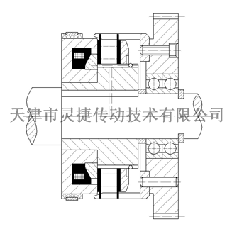
Installation Schematic
Installation Diagram
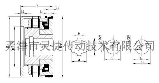
Outline and installation dimensions
Shape and Installation Dimensions

Specifications
ModelRadial Dimensions
Axial dimension Radial Dimensions
Brush model
D1
D2
D3
D
d
b
Φ
e
h
H1
L
L1
L2
L3
L4
DS-002
1.2
86
50
86
200 0.023
170 0.12
6 0.025 0.065
20
6
22.80 0.1
——
43.5
38
5.5
5
7
2.5
96
56
96
250 0.023
210 0.14
5 0.025 0.065
25
8
28.30 0.2
——
48.5
43
5.5
7
7
5
113
65
113
300 0.023
260 0.14
6 0.025 0.065
30
8
33.30 0.2
——
55.5
50
5.5
7
8
DS-001
10
133
75
133
400 0.027
350 0.17
10 0.035 0.085
40
12
43.30 0.2
——
61
54.5
6.5
8
10
16
145
85
145
450 0.027
400 0.17
12 0.045 0.105
45
14
48.80 0.2
——
63.5
57
6.5
8
10
25
166
95
166
500 0.027
450 0.17
12 0.045 0.105
50
14
53.80 0.2
——
72
64.5
7.5
10
10
40
192
120
192
600 0.030
540 0.20
14 0.045 0.105
60
18
64.40 0.2
——
82.5
74.5
8
10
10
63
212
125
212
700 0.030
620 0.20
16 0.045 0.105
70
20
74.90 0.2
——
91.5
82
9.5
12
10
100
235
150
235
——
——
——
70
20
74.90 0.2
——
105
96
10
15
10
160
270
180
270
——
——
——
100
28
106.40 0.2
——
118
104
14
15
10
250
310
220
310
——
——
——
110
28
116.40 0.2
122.80 0.4
130
116
14
10
12
400
415
235
415
——
——
——
120
32
127.40 0.2
134.80 0.4
150
132
18
10
12
1.2C
94
50
86
300 0.023
260 0.14
8 0.035 0.085
——
——
——
——
56
50.5
5.5
19
10
5C
116
65
113
400 0.027
350 0.17
10 0.035 0.023
——
——
——
——
59.5
54
5.5
19
10
10C
142
85
133
500 0.027
450 0.17
12 0.045 0.105
——
——
——
——
64.5
58
6.5
19
10
25C
176
105
166
650 0.030
580 0.20
16 0.045 0.105
——
——
——
——
81
73.5
7.5
21
10
DLM5 Series Wet Multi-disc Electromagnetic Clutch
Classification
Keyword
Multi-disc electromagnetic clutch
- Details
-
1) Since the engagement and disengagement of the electromagnetic clutch are carried out at high speed, there will be many traces of clutch on the iron suction plate and the surface of the rotor. These marks are not hazardous to work and are permitted. 2) Apply a suitable voltage to the electromagnetic coil. For a 12V voltage electromagnetic coil, if it is added to a 6V voltage system, it cannot generate enough magnetic field, which will cause the suction iron to slip, shorten the life of the clutch, and reduce the cooling capacity. Conversely, if a 6V coil is added to a 12V voltage system, the coil life will be shortened. 3) The gap between the coil and the rotor is very important. The coil and the rotor should be as close as possible to obtain a stronger magnetic field, but the gap should not be too small to prevent the rotor from dragging the coil (for the fixed-ring clutch). 4) The gap between the rotor and the suction iron is also very important. If this gap is too small, the rotor will drag the suction iron when the clutch is disengaged. However, if the gap is too large, there is too little contact between them when the clutch is operated. Both of these conditions can cause poor clutch performance. The reasonable gap between them should be that when the clutch has no current, the two do not drag; when the clutch has current, it can ensure that no slippage occurs.
1. Connection and cut-off action: installation between the driving part and the starting part does not need to stop the driving part, and the starting part will do connection and cut-off action according to the necessary reaction. 2. Speed change: there is a situation of mutual speed change during the operation. If the clutch is used at this time, the speed can be changed without closing the drive. 3. Positive and reverse rotation: When the load point is switched to positive and reverse rotation, it is only necessary to rotate in the forward direction when used with the clutch. 4. High-frequency operation: in the rapid cycle of intermittent operation, repeated use of the motor ON, OFF provided by the frequency is limited, so the use of clutch, so that rapid response, high-precision braking. 5. Inching: When the machine starts to operate and the position is engaged, it only needs to operate the clutch instantaneously.
Main performance parameters
Main Technical Data
Specifications
ModelRated dynamic torque
Rated Torque
N.MRated static moment
Rated Static Torque
N.Mno-load moment
Drag Torque
(≦) N.mOn time Engagement Time
(≦)SDisconnection time
Disengagement
(≦)SRated voltage
Rated Voltage
D.C.VCoil power consumption (20 ℃)
CoilPower
(20℃)WMaximum allowable speed
Max Allowed Speed
r/minWeight
Weight
KgOil supply flow
Oil Flow Rates
L/min1.2/1.2C
12
20
0.39
0.28
0.09
24
10
3500
1.3
0.20
2.5
25
40
0.40
0.30
0.09
24
17
3500
1.73
0.25
5/5C
50
80
0.9
0.32
0.10
24
17
3000
2.9
0.40
10/10C
100
160
1.80
0.35
0.14
24
19
3000
4.3
0.65
16
160
250
2.40
0.37
0.14
24
26
2500
5.53
0.65
25/25C
250
400
3.50
0.40
0.18
24
39
2200
8
1.00
40
400
630
5.60
0.42
0.20
24
45
2000
12.2
1.00
63
630
1000
9.00
0.45
0.25
24
66
1800
16.2
1.2
100
1000
1600
15.0
0.65
0.35
24
81
1600
23.2
1.2
160
1600
2500
24.0
0.90
0.45
24
87
1600
31.7
1.5
250
2500
4000
37.50
1.20
0.60
24
100
1200
47.1
2.0
400
4000
63000
60.00
1.50
0.80
24
134
1000
100.9
3.0
Installation Schematic
Installation Diagram
Outline and installation dimensions
Shape and Installation Dimensions

Specifications
ModelRadial Dimensions
Axial dimension Radial Dimensions
Brush model
D1
D2
D3
D
d
b
Φ
e
h
H1
L
L1
L2
L3
L4
DS-002
1.2
86
50
86
200 0.023
170 0.12
6 0.025 0.065
20
6
22.80 0.1
——
43.5
38
5.5
5
7
2.5
96
56
96
250 0.023
210 0.14
5 0.025 0.065
25
8
28.30 0.2
——
48.5
43
5.5
7
7
5
113
65
113
300 0.023
260 0.14
6 0.025 0.065
30
8
33.30 0.2
——
55.5
50
5.5
7
8
DS-001
10
133
75
133
400 0.027
350 0.17
10 0.035 0.085
40
12
43.30 0.2
——
61
54.5
6.5
8
10
16
145
85
145
450 0.027
400 0.17
12 0.045 0.105
45
14
48.80 0.2
——
63.5
57
6.5
8
10
25
166
95
166
500 0.027
450 0.17
12 0.045 0.105
50
14
53.80 0.2
——
72
64.5
7.5
10
10
40
192
120
192
600 0.030
540 0.20
14 0.045 0.105
60
18
64.40 0.2
——
82.5
74.5
8
10
10
63
212
125
212
700 0.030
620 0.20
16 0.045 0.105
70
20
74.90 0.2
——
91.5
82
9.5
12
10
100
235
150
235
——
——
——
70
20
74.90 0.2
——
105
96
10
15
10
160
270
180
270
——
——
——
100
28
106.40 0.2
——
118
104
14
15
10
250
310
220
310
——
——
——
110
28
116.40 0.2
122.80 0.4
130
116
14
10
12
400
415
235
415
——
——
——
120
32
127.40 0.2
134.80 0.4
150
132
18
10
12
1.2C
94
50
86
300 0.023
260 0.14
8 0.035 0.085
——
——
——
——
56
50.5
5.5
19
10
5C
116
65
113
400 0.027
350 0.17
10 0.035 0.023
——
——
——
——
59.5
54
5.5
19
10
10C
142
85
133
500 0.027
450 0.17
12 0.045 0.105
——
——
——
——
64.5
58
6.5
19
10
25C
176
105
166
650 0.030
580 0.20
16 0.045 0.105
——
——
——
——
81
73.5
7.5
21
10
Product inquiry

The company has a product research and development department composed of experts, senior engineers and other professional and technical personnel. It is engaged in research and development and has perfect research and development test equipment. At present, the products reach more than 100 series of nearly 1,000 specifications, and the force distance ranges from 0.1N. m ~ 250000N.m. The company has been rated as a high-tech enterprise by the state for more than ten consecutive years, and a number of R & D projects have been established locally and have received municipal financial support.
Service Hotline:
Sales Department: Xu Jie
Sales Phone:+86-22-26616372, +86-22-26341260, +86 13920613215
Fax: 86-022-26616580
Market Development Department: Li Shuo
Marketing Department Telephone:+86-22-26614130
Technology Department: Yue Chao
Technical Department Telephone:+86-22-26222775 ,+86 18602228435
QQ:1059237223 1611412939
Company Website:www.tjlhq.com
Enterprise E-mail:xzm@tjlhq.com
Company address: No.6, Zone B, South Jifeng Road, Hongcang City Industrial Park, Yanji Daohong, Beichen District, Tianjin


