Share
- Details
-
In order to ensure the uninterrupted operation of the electromagnetic clutch, it must be maintained and maintained frequently:
1. Always check the tightening degree of the bolts, especially tighten the bolts of the electromagnet, the bolts of the electromagnet and the housing, the bolts of the yoke, the bolts of the electromagnet coil and the terminal bolts.
2. Lubricant is often added to the movable part of the electromagnetic clutch.
3. Regularly check the mechanical wear of the movable parts, and remove the dust, flower hair and dirt on the surface of the electromagnet parts.
4. Regularly check the length of the armature stroke. This is because, during operation of the clutch, the stroke length of the armature will increase due to wear of the cutting surface. When the armature stroke length does not reach the normal value, it must be adjusted to restore the minimum gap between the braking surface and the turntable. If the armature stroke length is increased above the normal value, the suction force may be greatly reduced.
5. If the worn braking surface is replaced, the minimum clearance between the braking surface and the turntable should be properly adjusted.
During use, the electromagnetic clutch will have different failures due to various factors. The general failure of the electromagnetic clutch mostly occurs during starting, idling and load, but it occurs more often during the starting period, mainly manifested as failure to start, or the voltage input to the electromagnetic clutch is too low, and the regular input voltage is DC24V. As well as unstable power, slippage or high temperature, but there are also special circumstances.
Therefore, pay attention to the requirements when inputting the voltage. The elimination method is to detect whether the input voltage is the required voltage of the electromagnetic clutch. The coil is short-circuited, and this kind of fault is usually replaced or repaired. It is recommended to replace or modify the electromagnetic clutch circuit.Main performance parameters
Main Technical DataSpecifications
ModelRated dynamic torque
Rated Torque
(N.M)Rated static moment
Rated Static Torque N.mno-load moment
Drag Torque
(≦) N.mOn time
Engagement Time
(≦)SDisconnection time
Disengagement Time
(≦)SRated voltage
Rated Voltage
D.C(V)Coil power consumption (20 ℃)
Coilpower(20℃)WMaximum allowable speed
Max Allowed Speed(r/min)Weight
weighnt(kg)1A/1A.G
12.5
20/14
0.088/0.05
0.14/0.11
0.03/0.025
24
26
3000
2
2A/2A.G
25
40/27.5
0.175/0.10
0.18/0.14
0.032/0.028
24
27
3000
2.6
4A/4A.G
40
63/44
0.280/0.16
0.20/0.18
0.04/0.03
24
33
3000
3.2
6A/6A.G
63
100/70
0.350/0.26
0.25/0.20
0.045/0.04
24
43
3000
4
10A/10A.G
100
160/110
0.500/0.35
0.28/0.25
0.06/0.045
24
43
3000
5.5
16A/16A.G
160
250/175
1.00/0.56
0.30/0.28
0.08/0.06
24
47
2500
7.8
25A/25A.G
250
400/280
1.50/0.88
0.35/0.30
0.11/0.08
24
55
2200
11
40A/40A.G
400
630/440
2.50/1.40
0.40/0.35
0.12/0.11
24
62
2000
15
63A/63A.G
630
1000/700
4.00/2.20
0.50/0.40
0.15/0.12
24
70
1750
21
100A/100A.G
1000
1600/1100
6.00/3.00
0.60/0.50
0.18/0.15
24
79
1600
32
160A/160A.G
1600
2500/1750
10/5.5
0.90/0.70
0.22/0.18
24
93
1350
50
250A/250A
2500
4000/2750
15/8.6
1.15/0.90
0.28/0.25
24
110
1200
77
400A/400A.G
4000
6300/4400
24/14
1.30/1.20
0.35/0.30
24
123
1000
122
630A.G
6300
6800
22.5
2.1
0.4
24
137
900
194
1000A.G
10000
11000
36
3.6
0.6
24
180
750
300
Note: G is dry multi-disc electromagnetic clutch
Note: G express the electromagnetic multidisc clutch of dry operationInstallation Schematic
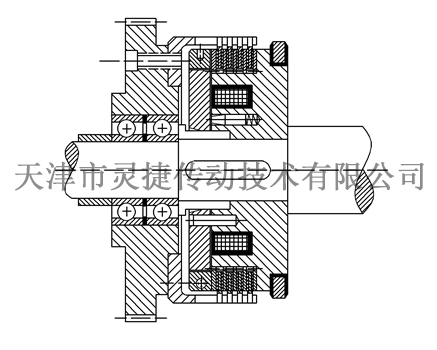
Installation Diagram

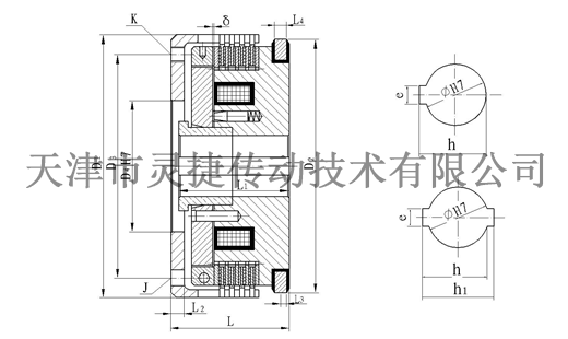
Outline and installation dimensions
Shape and Installation Dimensions

Specifications
ModelRadial Dimensions
Axial dimension
Axial DimensionsBrush model
Brush ModelD1
D2
D3
D4
Φ
e
h
J
K
L
L1
L2
L3
L4
E
1A/ 1A.G
100
100
85
50
18
50 0.025
19.9 0.14
2Xφ6
4XM6
45
42
5
5.5
8
0.30
wet
Adopt
DS-005
dry type
Adopt
DS-006
2A/ 2A.G
110
110
90
55
20
60 0.025
22.3 0.14
2Xφ6
4XM6
48
45
5
5.5
8
0.30
4A/ 4A.G
120
120
100
60
25
80 0.03
27.6 0.14
3Xφ6
6XM6
52
48
6
5.5
8
0.30
6A/6A.G
132
132
105
65
30
80 0.03
32.6 0.17
3Xφ6
6XM8
55
50
7
5.5
8
0.30
10A/ 10A.G
147
145
120
75
40
120 0.035
42.9 0.17
3Xφ8
6XM8
58
53
7
5.5
8
0.35
16A/ 16A.G
162
160
135
85
45
140 0.035
48.3 0.17
3Xφ8
6XM8
62
57
7
5.5
8
0.40
25A/ 25A.G
182
180
155
95
50
160 0.035
53.60 0.20
3Xφ10
6X M10
68
63
8
6
8
0.45
40A/ 40A.G
202
200
170
120
60
180 0.035
64 0.20
3Xφ10
6X M10
76
70
9
6.25
8
0.50
63A/ 63A.G
235
230
200
125
70
200 0.0435
74.3 0.20
3Xφ14
6X M12
86
80
10
6.25
8
0.60
100A/ 100A.G
270
255
235
150
70
200 0.0435
74.3 0.20
3Xφ14
6X M12
100
92
12
8.5
10
0.70
160A/ 160A.G
310
295
260
180H8
75
20±0.026
81.1 0.20
3Xφ16
6X M16
115
107
14
8
10
0.80
250A/ 250A.G
360
340
305
200H8
100
28±0.026
106.4 0.20
3Xφ16
6X M16
132
122
15
8.5
10
0.90
400A/ 400A.G
420
395
350
235H8
120
320 0.05
126.7 0.20
4Xφ20
6X M16
150
138
17
8.5
10
1
630A.G
485
455
400
235 H8
130
32 0.01 0.07
136.7 0.20
4Xφ20
8X M20
172
157
20
10.5
12
1.1
1000A.G
560
530
460
280
145
32±0.03
154.2 0.20
4Xφ25
4X M24
200
183
22
10.5
12
1.3.
Note: 1. D3, J and K listed in the table are user connection dimensions, which are processed by the user. The data in this table are for reference only.
2.250A/250AG,400A/ 400A.G, 630A.G, 1000A.G,G is a double bond hole, the position is 180, h1 is 112.80 0.2,113.40 0.52,143.40 0.52,163.40 0.2
Remark:1. D3、J、K list in the list are sizes using for join of customer and processed by customer himself. The data of this list are for reference only
2. 250A/250AG,400A/ 400A.G、630A.G、1000A.G,G are double-Kay hole. The position in 180°,h1 is 112.8 plus0 0.2,133.4 plus0 0.52,143.4 plus0 0.52,163.4 plus0 0.2
DLM10 Series (EKE Series) Multi-disc Electromagnetic Clutch
Classification
Keyword
Multi-disc electromagnetic clutch
- Details
-
In order to ensure the uninterrupted operation of the electromagnetic clutch, it must be maintained and maintained frequently:
1. Always check the tightening degree of the bolts, especially tighten the bolts of the electromagnet, the bolts of the electromagnet and the housing, the bolts of the yoke, the bolts of the electromagnet coil and the terminal bolts.
2. Lubricant is often added to the movable part of the electromagnetic clutch.
3. Regularly check the mechanical wear of the movable parts, and remove the dust, flower hair and dirt on the surface of the electromagnet parts.
4. Regularly check the length of the armature stroke. This is because, during operation of the clutch, the stroke length of the armature will increase due to wear of the cutting surface. When the armature stroke length does not reach the normal value, it must be adjusted to restore the minimum gap between the braking surface and the turntable. If the armature stroke length is increased above the normal value, the suction force may be greatly reduced.
5. If the worn braking surface is replaced, the minimum clearance between the braking surface and the turntable should be properly adjusted.
During use, the electromagnetic clutch will have different failures due to various factors. The general failure of the electromagnetic clutch mostly occurs during starting, idling and load, but it occurs more often during the starting period, mainly manifested as failure to start, or the voltage input to the electromagnetic clutch is too low, and the regular input voltage is DC24V. As well as unstable power, slippage or high temperature, but there are also special circumstances.
Therefore, pay attention to the requirements when inputting the voltage. The elimination method is to detect whether the input voltage is the required voltage of the electromagnetic clutch. The coil is short-circuited, and this kind of fault is usually replaced or repaired. It is recommended to replace or modify the electromagnetic clutch circuit.Main performance parameters
Main Technical DataSpecifications
ModelRated dynamic torque
Rated Torque
(N.M)Rated static moment
Rated Static Torque N.mno-load moment
Drag Torque
(≦) N.mOn time
Engagement Time
(≦)SDisconnection time
Disengagement Time
(≦)SRated voltage
Rated Voltage
D.C(V)Coil power consumption (20 ℃)
Coilpower(20℃)WMaximum allowable speed
Max Allowed Speed(r/min)Weight
weighnt(kg)1A/1A.G
12.5
20/14
0.088/0.05
0.14/0.11
0.03/0.025
24
26
3000
2
2A/2A.G
25
40/27.5
0.175/0.10
0.18/0.14
0.032/0.028
24
27
3000
2.6
4A/4A.G
40
63/44
0.280/0.16
0.20/0.18
0.04/0.03
24
33
3000
3.2
6A/6A.G
63
100/70
0.350/0.26
0.25/0.20
0.045/0.04
24
43
3000
4
10A/10A.G
100
160/110
0.500/0.35
0.28/0.25
0.06/0.045
24
43
3000
5.5
16A/16A.G
160
250/175
1.00/0.56
0.30/0.28
0.08/0.06
24
47
2500
7.8
25A/25A.G
250
400/280
1.50/0.88
0.35/0.30
0.11/0.08
24
55
2200
11
40A/40A.G
400
630/440
2.50/1.40
0.40/0.35
0.12/0.11
24
62
2000
15
63A/63A.G
630
1000/700
4.00/2.20
0.50/0.40
0.15/0.12
24
70
1750
21
100A/100A.G
1000
1600/1100
6.00/3.00
0.60/0.50
0.18/0.15
24
79
1600
32
160A/160A.G
1600
2500/1750
10/5.5
0.90/0.70
0.22/0.18
24
93
1350
50
250A/250A
2500
4000/2750
15/8.6
1.15/0.90
0.28/0.25
24
110
1200
77
400A/400A.G
4000
6300/4400
24/14
1.30/1.20
0.35/0.30
24
123
1000
122
630A.G
6300
6800
22.5
2.1
0.4
24
137
900
194
1000A.G
10000
11000
36
3.6
0.6
24
180
750
300
Note: G is dry multi-disc electromagnetic clutch
Note: G express the electromagnetic multidisc clutch of dry operationInstallation Schematic
Installation Diagram

Outline and installation dimensions
Shape and Installation Dimensions

Specifications
ModelRadial Dimensions
Axial dimension
Axial DimensionsBrush model
Brush ModelD1
D2
D3
D4
Φ
e
h
J
K
L
L1
L2
L3
L4
E
1A/ 1A.G
100
100
85
50
18
50 0.025
19.9 0.14
2Xφ6
4XM6
45
42
5
5.5
8
0.30
wet
Adopt
DS-005
dry type
Adopt
DS-006
2A/ 2A.G
110
110
90
55
20
60 0.025
22.3 0.14
2Xφ6
4XM6
48
45
5
5.5
8
0.30
4A/ 4A.G
120
120
100
60
25
80 0.03
27.6 0.14
3Xφ6
6XM6
52
48
6
5.5
8
0.30
6A/6A.G
132
132
105
65
30
80 0.03
32.6 0.17
3Xφ6
6XM8
55
50
7
5.5
8
0.30
10A/ 10A.G
147
145
120
75
40
120 0.035
42.9 0.17
3Xφ8
6XM8
58
53
7
5.5
8
0.35
16A/ 16A.G
162
160
135
85
45
140 0.035
48.3 0.17
3Xφ8
6XM8
62
57
7
5.5
8
0.40
25A/ 25A.G
182
180
155
95
50
160 0.035
53.60 0.20
3Xφ10
6X M10
68
63
8
6
8
0.45
40A/ 40A.G
202
200
170
120
60
180 0.035
64 0.20
3Xφ10
6X M10
76
70
9
6.25
8
0.50
63A/ 63A.G
235
230
200
125
70
200 0.0435
74.3 0.20
3Xφ14
6X M12
86
80
10
6.25
8
0.60
100A/ 100A.G
270
255
235
150
70
200 0.0435
74.3 0.20
3Xφ14
6X M12
100
92
12
8.5
10
0.70
160A/ 160A.G
310
295
260
180H8
75
20±0.026
81.1 0.20
3Xφ16
6X M16
115
107
14
8
10
0.80
250A/ 250A.G
360
340
305
200H8
100
28±0.026
106.4 0.20
3Xφ16
6X M16
132
122
15
8.5
10
0.90
400A/ 400A.G
420
395
350
235H8
120
320 0.05
126.7 0.20
4Xφ20
6X M16
150
138
17
8.5
10
1
630A.G
485
455
400
235 H8
130
32 0.01 0.07
136.7 0.20
4Xφ20
8X M20
172
157
20
10.5
12
1.1
1000A.G
560
530
460
280
145
32±0.03
154.2 0.20
4Xφ25
4X M24
200
183
22
10.5
12
1.3.
Note: 1. D3, J and K listed in the table are user connection dimensions, which are processed by the user. The data in this table are for reference only.
2.250A/250AG,400A/ 400A.G, 630A.G, 1000A.G,G is a double bond hole, the position is 180, h1 is 112.80 0.2,113.40 0.52,143.40 0.52,163.40 0.2
Remark:1. D3、J、K list in the list are sizes using for join of customer and processed by customer himself. The data of this list are for reference only
2. 250A/250AG,400A/ 400A.G、630A.G、1000A.G,G are double-Kay hole. The position in 180°,h1 is 112.8 plus0 0.2,133.4 plus0 0.52,143.4 plus0 0.52,163.4 plus0 0.2
Product inquiry

The company has a product research and development department composed of experts, senior engineers and other professional and technical personnel. It is engaged in research and development and has perfect research and development test equipment. At present, the products reach more than 100 series of nearly 1,000 specifications, and the force distance ranges from 0.1N. m ~ 250000N.m. The company has been rated as a high-tech enterprise by the state for more than ten consecutive years, and a number of R & D projects have been established locally and have received municipal financial support.
Service Hotline:
Sales Department: Xu Jie
Sales Phone:+86-22-26616372, +86-22-26341260, +86 13920613215
Fax: 86-022-26616580
Market Development Department: Li Shuo
Marketing Department Telephone:+86-22-26614130
Technology Department: Yue Chao
Technical Department Telephone:+86-22-26222775 ,+86 18602228435
QQ:1059237223 1611412939
Company Website:www.tjlhq.com
Enterprise E-mail:xzm@tjlhq.com
Company address: No.6, Zone B, South Jifeng Road, Hongcang City Industrial Park, Yanji Daohong, Beichen District, Tianjin


